
sales06@switek.biz

+86 186 5927 5869

Shopping

Subscrib to Us
sales06@switek.biz
+86 186 5927 5869
Shopping
Subscrib to Us

Keywords:Panasonic A6 Servo Installation Instruction, Panasonic A6 Driver, Panasonic A6 Series Servo Motor Manual
To change the monitor display setting, select the display option to be changed from "
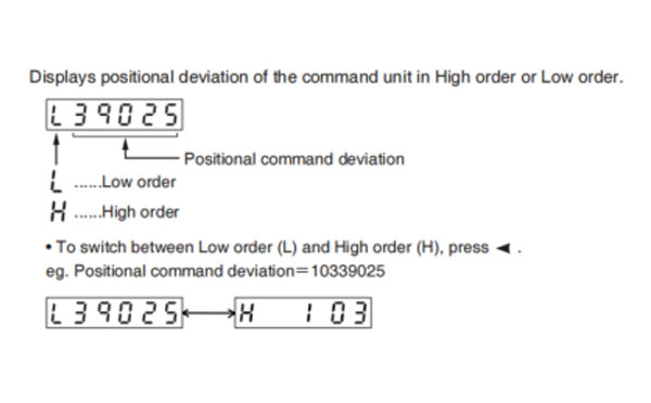
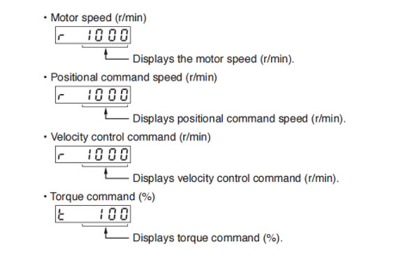
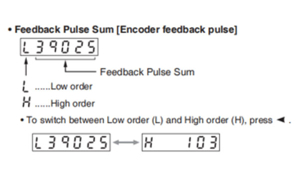
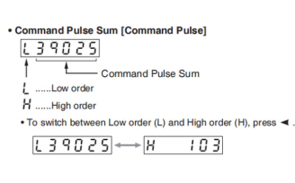
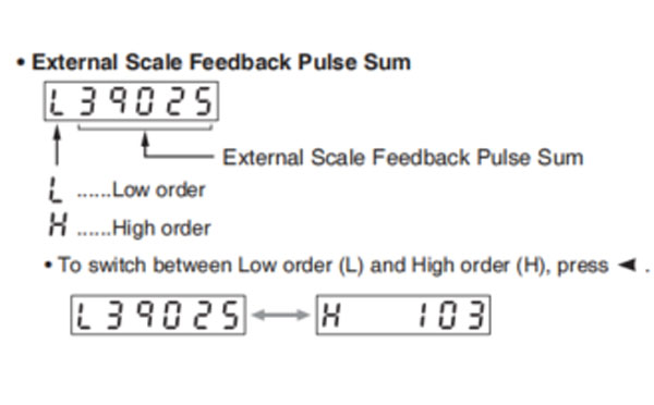
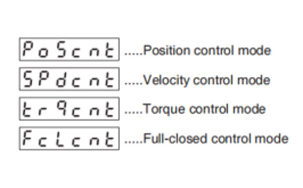
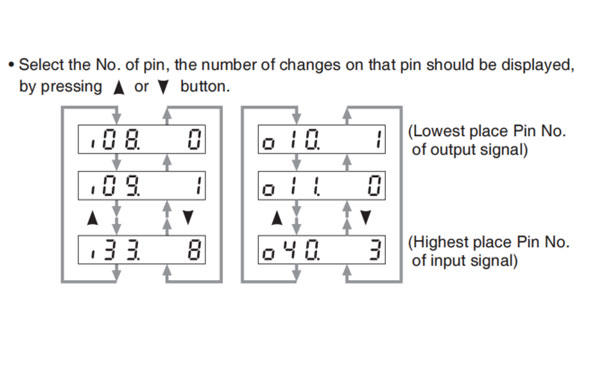
Displays the control input and output signal to be connected to connector X4. Use this function to check if the wiring is correct or not.
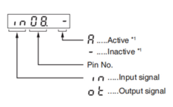
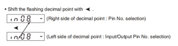
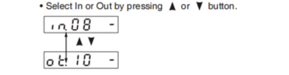
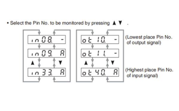
*1 When input signal Active: Input signal photocoupler is ON. Inactive: Input signal photocoupler is OFF.
When output signal Active: Output signal transistor is ON. Inactive: Output signal transistor is OFF.
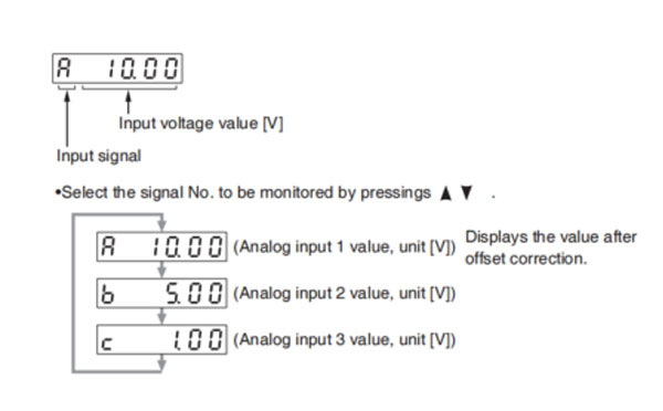
Caution → Voltage exceeding ±10 V can not be displayed correctly
Note → For detail of input/output signal, refer to P.3-33 "Inputs and outputs on connector X4"
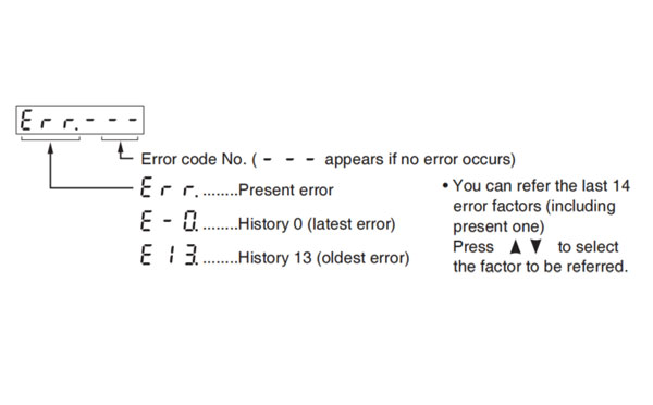
For detail of Error Code, refer to P.6-2 "Protective Function".
<List of error code No.>
| Error code | Protective function | Attribute | |||
|---|---|---|---|---|---|
| Main | Sub | History | Can be cleared | Immediate stop | |
| 11 | 0 | Control power supply under-voltage protection | ◯ | ||
| 12 | 0 | Over-voltage protection | ◯ | ◯ | |
| 13 | 0 | Main power supply under-voltage protection (between P to N) | ◯ | ||
| 1 | Main power supply under-voltage protection (AC interception detection) | ◯ | ◯ | ||
| 14 | 0 | Over-current protection | ◯ | ||
| 1 | IPM error protection | ◯ | |||
| 15 | 0 | Over-heat protection | ◯ | ◯ | |
| 1 | Encoders abnormal over-heat protection | ◯ | ◯ | ||
| 16 | 0 | Over-load protection | ◯ | ◯ | Suitable |
| 1 | Torque saturation anomaly protection | ◯ | ◯ | ||
| 18 | 0 | Over-regeneration load protection | ◯ | ◯ | |
| 1 | Over-regeneration Tr error protection | ◯ | |||
| 21 | 0 | Encoder communication disconnect error protection | ◯ | ||
| 1 | Encoder communication error protection | ◯ | |||
| 23 | 0 | Encoder communication data error protection | ◯ | ||
| 24 | 0 | Position deviation exccess protection | ◯ | ◯ | ◯ |
| 1 | Velocity deviation excess protection | ◯ | ◯ | ◯ | |
| 25 | 0 | Hybrid deviation excess error protection | ◯ | ◯ | |
| 26 | 0 | Over-speed protection | ◯ | ◯ | ◯ |
| 1 | 2nd over-speed protection | ◯ | ◯ | ||
| 27 | 0 | Command pulse input frequency error protection | ◯ | ◯ | ◯ |
| 1 | Absolute clear abnormal protection | ◯ | |||
| 2 | Command pulse multiplier error protection | ◯ | ◯ | ◯ | |
| 28 | 0 | Limit of pulse replay error protection | ◯ | ◯ | ◯ |
| 29 | 0 | Deviation counter overflow abnormality protection | ◯ | ◯ | |
| 1 | Counter overflow protection 1 | ◯ | |||
| 2 | Deviation counter overflow abnormality protection 2 | ◯ | |||
| 31 | 0 | Safety function error protection 1 | ◯ | ||
| 2 | Safety function error protection 2 | ◯ | |||
| 33 | 0 | IF overlaps allocation error 1 protection | ◯ | ||
| 1 | IF overlaps allocation error 2 protection | ◯ | |||
| 2 | IF input function number error 1 protection | ◯ | |||
| 3 | IF input function number error 2 protection | ◯ | |||
| 4 | IF output function number error 1 protection | ◯ | |||
| 5 | IF output function number error 2 protection | ◯ | |||
| 6 | CL fitting error protection | ◯ | |||
| 7 | INH fitting error protecdtion | ◯ | ◯ | ||
| 34 | 0 | Software limit protection | ◯ | ◯ | |
| 36 | 0 to 1 | EEPROM parameter error protection | |||
| 37 | 0 to 2 | EEPROM check code error protection | |||
| 38 | 0 | Over-travel inhibit input protection | ◯ | ||
| 39 | 0 | Analog input 1 excess protection | ◯ | ◯ | ◯ |
| 1 | Analog input 2 excess protection | ◯ | ◯ | ◯ | |
| 2 | Analog input 3 excess protection | ◯ | ◯ | ◯ | |
| 40 | 0 | Absolute system down error protection | ◯ | ◯ | |
| 41 | 0 | Absolute counter over error protection | ◯ | ||
| 42 | 0 | Absolute over-speed error protection | ◯ | ◯ | |
| 43 | 0 | Initialization failure | ◯ | ||
| 44 | 0 | Absolute single turn counter error protection | ◯ | ||
| 45 | 0 | Absolute multi-turn counter error protection | ◯ | ||
| 47 | 0 | Absolute status error protecdtion | ◯ | ||
| 48 | 0 | Encoder Z-phase error protection | ◯ | ||
| 49 | 0 | Encoder CS signal error protection | ◯ | ||
| 50 | 0 | External scale connection error protection | ◯ | ||
| 1 | External scale communication error protection | ◯ | |||
| 51 | 0 | External scale status 0 error protection | ◯ | ||
| 1 | External scale status 1 error protection | ◯ | |||
| 2 | External scale status 2 error protection | ◯ | |||
| 3 | External scale status 3 error protection | ◯ | |||
| 4 | External scale status 4 error protection | ◯ | |||
| 5 | External scale status 5 error protection | ◯ | |||
| 55 | 0 | A-phase connection error protection | ◯ | ||
| 1 | B-phase connection error protection | ◯ | |||
| 2 | Z-phase connection error protection | ◯ | |||
| 70 | 0 | U-phase current detector error protection | ◯ | ||
| 1 | W-phase current detector error protection | ◯ | |||
| 72 | 0 | Thermal error | ◯ | ||
| 80 | 0 | Modbus communications timeout protection | ◯ | ◯ | ◯ |
| 87 | 0 | Compulsory alarm input protection | ◯ | ◯ | |
| 92 | 0 | Encoder data recovery abnormal protection | ◯ | ||
| 3 | Multi-turn data upper-limit value disagreement error protection | ◯ | |||
| 93 | 0 | Parameter setting error protection 1 | ◯ | ||
| 1 | Block data setting error protection | ◯ | ◯ | ||
| 2 | Parameter setting error protection 2 | ◯ | |||
| 3 | External scale connection error protection | ◯ | |||
| 8 | Parameter setting error protection 6 | ◯ | |||
| 94 | 0 | Block operation error protection | ◯ | ◯ | |
| 2 | Return to origin error protection | ◯ | ◯ | ||
| 95 | 0 to 4 | Motor automatic recognition error protection | |||
| 97 | 0 | Control mode setting error protection | |||
| 97 | 0 | Control mode setting error protection | |||
| Other number | Other error | ◯ | |||
History... The error will be stored in the error history.
Can be cleared... To cancel the error, use the alram clear input (A-CLR).
If the alarm clear input is not effective, turn off power, remove the cause of the error and then turn on power again.
Immediate stop... Instantaneous controlled stop upon occurrence of an error. (Setting of "Pr.5.10 Sequence at alarm" is also required.)
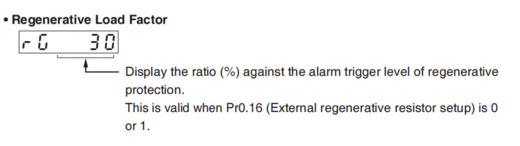
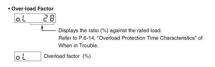
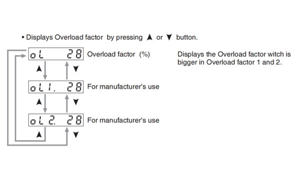
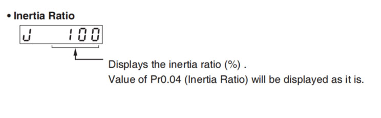
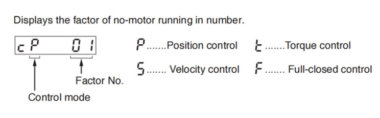
| Factor No. | Factor | Related Control Mode | Content | |||
|---|---|---|---|---|---|---|
| P | S | T | F | |||
| flashing | Occurrence of error/alarm | ◯ | ◯ | ◯ | ◯ | An error is occurring, and an alarm is triggered. |
| 00 | No particular factor | ◯ | ◯ | ◯ | ◯ | No factor is detected for No-motor run. The motor runs in normal case. |
| 01 | Main power shutoff | ◯ | ◯ | ◯ | ◯ | The main power of the driver is not turned on. |
| 02 | No entry of SRV-ON input | ◯ | ◯ | ◯ | ◯ | The Servo-ON input (SRV-ON) is not connected to COM-. |
| 03 | Over-travel inhibition input is valid | ◯ | ◯ | ◯ | ◯ | While Pr5.04 is 0 (Run-inhibition input is valid),
|
| 04 | Torque limit setup is small | ◯ | ◯ | ◯ | ◯ | Either one of teh valid torque limit setup value of Pr0.13 (1st) or Pr5.22 (2nd) is set to 5% or lower than the rating. |
| 05 | Analog torque limit input is valid. | ◯ | ◯ | ◯ | While Pr5.21 is 0 (analog torque limit input accepted),
| |
| 06 | INH input is valid. | ◯ | ◯ | Pr5.18 is 0 (Command pulse inhibition input is valid.), and INH is open. | ||
| 07 | Command pulse input frequency is low. | ◯ | ◯ | The position command per each control cycle is 1 pulse or smaller due to,
| ||
| 08 | CL input is valid. | ◯ | ◯ | While Pr5.17 is 0 (Deviation counter clear at level), the deviation counter clear input (CL) is connected to COM-. | ||
| 09 | ZEROSPD input is valid | ◯ | ◯ | While Pr3.15 is 1 (Speed zero clamp is valid.), the speed zero clamp input (ZEROSPD) is open. | ||
| 10 | External speed command is small. | ◯ | While the analog speed command is selected, the analog speed command is smaller than 0.06[V]. | |||
| 11 | Internal speed command is 0. | ◯ | While the internal speed command is selected, the internal speed command is set to lower than 30[r/min] | |||
| 12 | Torque command is small. | ◯ | The analog torque command input (SPR or P-ATL) is smaller than 5 [%] of the rating. | |||
| 13 | Speed limit is small. | ◯ |
| |||
| 13 | Speed limit is small | ◯ |
| |||
Note → *Motor might run even though the other number than 0 is displayed. Refer to "6. In trouble".
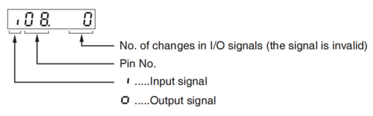
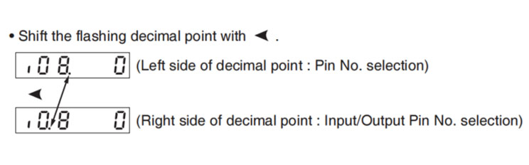
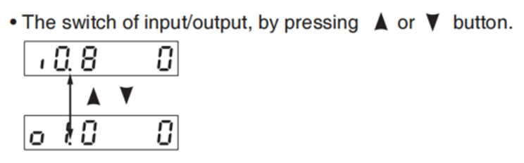
4 Cavities Direct Connectors Runner Cutting Solution


